Saturday 28 April 2007

Brake Pipes Finished - Fuel Line Not....

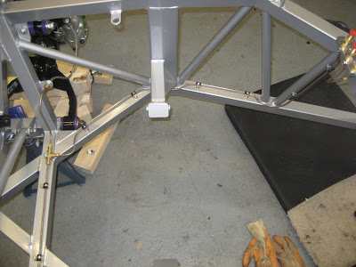
Set to work drilling holes in the chassis and fitting rivet nuts and rubber lined p-clips for the brake pipes. All the chassis members that were drilled into were waxoiled through the drilled holes before fitting the rivet nuts. A fairly neat result:
I also bent a fitted the rear brake feed. Like other people I found this pipe to be a little on the long side which results with a bit of a "loop" by the union block. However there should be plenty of clearance to the clutch bellhousing - in hindsight it would have been easier not to use the brake pipe kit supplied but to make them up myself - might still have to do this if clearance is a problem?

I also bent to shape the rigid fuel line (10mm and a real thumb killer!) - However the p-clips supplied are 9mm... for a 10mm pipe! - I'll have to get some before I can fix this, so at the moment it is held in place with masking tape:

The engine doesn't arrive until w/c 17th June - that's 7 weeks away with not that many things to be doing! All I have on the to-do list at the minute is:
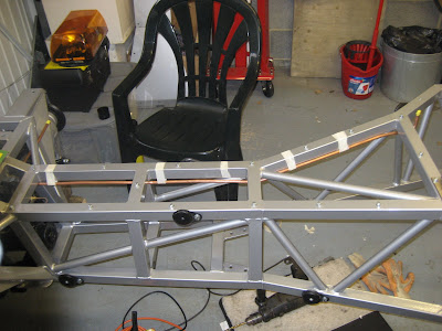
  • Fit the replacement track rod ends and set the front end up (again)..... I'm still waiting for the track rod ends from GD!
  • Clip the fuel line into place - need the right clips and to sort out clip spacing.
  • Fill the diff with Oil.
  • Fit some external return springs on the handbrake mechanism.
  • Fit jaguar wheels ready for engine / gearbox install (should be getting them next week - thanks again Lee).
  • Obtain all the parts that I need for the engine install stage and prior to recieving the body(propshaft, speedo cable, throttle cable and bracket, handbrake cable, radiator, twin fan kit, coolant header tank, oil cooler, coolant hoses, exhaust system, gearbox mounting bracket and anything else I've forgotten!).

So I think I'll spend the next few weeks sourcing parts - GD can supply everything you need - with some parts this is important to ensure compatibility - but there must be plenty of items that I can get cheaper elsewhere?

Still doesn't seem like enough to fill seven weeks? - I feel some garage tidying coming on!


Tuesday 24 April 2007

Undoing the undone

Having had to take the steering arms off to get the track rod ends out I needed to put them back. As I have now got my hands on some more lockwire I was able to do this. All I need now are my replacement track rod ends.... still waiting.....

I also received my latest addition to the tool family today .... a blind, nut and stud riveting set. So now I can fit some rivet nuts and fix the brake pipes to the chassis members.

I'm getting towards the point where I am going to need some wheels to start moving the chassis about. I posted a message on the cobraclub forum to see if anyone had any surplus to requirements jag wheels. Turns out a chap from North Yorkshire comes up this way on business and has offered to meet up next week.. Thanks Lee.

Just need to pluck up some courage to start drilling holes in my nice shiny chassis!

Monday 23 April 2007

Engine Ordered

I finalised the details of my engine with Ian Briggs of British American Engines today and the order was made!! Build will start on Monday the 11th of June and will finish on the Friday with a test run to break in the camshaft and check everything else is OK. This will be videoed so I'll be able to post it here later.

So week commencing 18th June should see one of these in my Garage:

Only with the block painted Red.

Then will follow the fun of installing it (and the gearbox) into the chassis!

More Brake Pipes

After the pivot brackets - seeing as I was in the mood for doing things I'd been putting off - I thought I'd do the front brake pipe feed. As the pipes are made up and of fixed length it was going to be tricky to get it to fit as it followed a slightly tortuous route.

Anyways, after a lot of bend it, try it, bend it, try it etc..... the job was done - reasonably neatly as well as a bonus!
You can see that the pipe is held in place with masking tape at the minute - I need to get a rivet nut gun so I can fix the pipe clips to the chassis. I could just rivet the clips in place - but bolting them into rivet nuts allows the pipes to be easily removed. It's nice to have such confidence in one's own work!

Forgotten Job....

When I part stripped the rear end to correct the diff bracket shims I forgot to lockwire the pivot bracket bolts as I was too eager to check the geometry. I hadn't really forgot about it .... I just kept putting it off 'cos I knew it was going to be a Pain the A. As the chassis is up on axle stands (and I'll probably have to put it back down to re-do the front) I thought I'd better get on with it.

So an hour of mucking about later job done - shame it would have only taken 5 minutes if I'd remembered to do it at the right time!

Thursday 19 April 2007

Engine Decisions

I've been studying all the bumph sent to me by British American Engines.
I've basically got two choices:

1) 383 stroker 375 bhp & 395 lbft
or
2) 383 stroker 425 bhp and 470lbft

Option 2 is going to be on the limit of budget.
Option 1 is close to my original target of 400 bhp and 400 ftlb.
Option 1 leaves some spare budget for extra shiny bits.

The extra shiny bits have it!! option 1 it is

So the Specs would be:
383 stroker built on a pre 1993 seasoned block (pre 93 to avoid emissions tests!).
375 bhp and 395 ftlb with 9.5:1 compression ratio.
600cfm Edelbrock Performer Carburetor (manual choke - may well remove the choke):
Edelbrock inlet manifold:Custom Ground Camshaft.
Dual Roller Timing Chain
MSD Magnetic Billet Distributor:
MSD6AL Ignition System:
Edelbrock Performer RPM Aluminium Heads:

Hypereutectic Pistons
Eagle Crankshaft
Eagle Rods
Fullreciprocating Balance
Edelbrock Elite Alloy Valve Covers:


Edelbrock Elite Air Filter:

Brushed Aluminium Ignition Guide Rails.

Show Quality Two Pack Paint to Block (colour matched for body colour)

Hi-torque Mini Starter.


And not forgetting a Tremec TKO 600 Gearbox with uprated clutch, flywheel, fork arm, thrust bearing and slave cylinder:

And on my super new build programme I need to order this in the next couple of weeks!

Now where's my replacement track rod ends?

Build Programme

You will notice under the picture in the right hand side bar a link to the build programme. This is pretty rudimentary at this stage but was done to give me an idea of how long things were going to take & when I needed to order bits.

In theory it looks like in just about 2 years from today all will be finished!! (only time will tell). Some of the build activities may seem to have longer durations but this is primarily a function of cash flow rather than time required. I haven't as yet delved into the build process in any great detail rather just looked at the basics.

As usual I reserve the right to completely change my mind and do something completely different!

Monday 16 April 2007

Engine Progress!

Having decided that I was going to cheat and get someone else to build an engine for me (big girls blouse that I am!) I've been making a few enquiries recently. I've settled on British American Engines and was speaking to Ian Briggs today - VERY helpful chap. He agreed that my intention to go for a 383 (stroked 350 chevy) was a good one and he has sent up some engine spec sheets and quotes for me to decide.

Engine delivery will take 5-6 weeks from order which was quicker than I expected so I've got some time in hand yet. They will also supply the Tremec TKO 600 Gearbox that I am after and will also dial in the bell housing and fit the clutch as part of the build.

I just need to decide what extra shiny bits I want?

More news when I've made my mind up.

That's cheered me up after the track rod end fiasco!

Track Rod End Woes...

Spoke to Andy at GD today and he confirmed that something was not right. He suspects that the taper pins on the track rod ends are undersize. He will sort out some replacements but asked if I could send the old ones back for him to look at.

So, no time like the present so I decided to remove them - problem was that they were a snug fit in the steering arms - I ended up removing the lockwiring to remove the steering arms so I could press the track rod ends out. This also entailed removing the springs and essentially undoing most of what I achieved the other day!

Sunday 15 April 2007

Bend it like......

Still a trifle downbeat today - thinking about track rod ends. So time for something simple. I removed the transmission tunnel sheet, radiator support frame and body mountings so I could Waxoyl the inside of the chassis tubes. However judging by the smell from inside the tubes this may have already been done. A bit monotonous feeding the spray tube through the fixing holes - but well worth doing.

I felt like doing something else so I thought I would start fitting some of the brake pipes. I fitted the brake union mounting block, front splitter and the two pipes to the front callipers:
All pretty easy as each only has two bends in a straight line (note the longer pipe requires fixing to the chassis yet)

Next step was to fit the rear splitter and the two pipes to the rear calipers - these were awkward little buggers - short with tight bends.
I cheated my making a template out of a scrap piece of copper pipe and then using that as a guide to bend the pipe supplied by GD (fixed length with fittings on the end). It was important to ensure that the brake pipes cleared the handbrake calipers as shown:


I'm not sure how you will ever get back to these with the body on? Might have to devise a way of checking the integrity of the pipe runs as the pedal box is fitted to the body so you can't check the whole system until the body is on.

Hopefully tomorrow I'll find out what is wrong with my track rod ends?

Saturday 14 April 2007

Four Wheels on my Wagon....

As this weekend was one of the rare occasions that we weren’t away I managed to spend a whole day in the garage. The first task was to centre the steering rack, fit the trackrod ends and set the front toe in (more on trackrod ends later). To check the toe in a 1m long aluminium angles was clamped to the face of each hub – centred about the hub and set horizontal. The distances between the front and rear ends were then measured and the track rods adjusted accordingly. GD specify 0-1.5mm toe in over a wheel width – I set the front wheels to 2mm toe in over 1m.
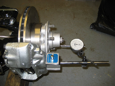
Having set the total toe in – the front wheels then needed to be aligned to the rear wheels by making reference to the line of thrust determined earlier. The aluminium box section was clamped over the rear hubs with the centreline of chassis, rear hubs and thrust line offset marked on it. The trusty laser level was then clamped to the face of the front hub and projected back to the box section. The track rod ends were then adjusted by equal but opposite amounts until the laser dots where equidistant from the line of thrust mark. The angles were then replaced on the hubs and the total toe-in checked again and adjusted slightly. The laser was then used again to check the alignment relative the line of thrust – all OK.

So we’ve now got four wheels all pointing in the same direction! The next thing to do was to adjust the steering rack to eliminate bump steer. This was done by clamping one of the angles to the hub face with the other placed on the floor and aligned to it with the top wishbone horizontal (normal ride attitude):
A jack under the lower wishbone was then used to move the suspension through it’s full range of movement (13” between damper fixing holes for full droop and 10” between holes for full bump). The steering rack needed to be adjusted so that the two angles remained parallel throughout the full suepension range.

After a fair bit of faffing about the steering rack ended up right at the top of it’s adjustment and this was good for all but the last ¼ of an inch of bump or droop – there was no adjustment left? (see track rod ends later).

The next job was to fit the front springs and dampers – followed by the brake pads – all quite simple with no problems. Having completed the front end (hopefully) I noted that the steering seemed fairly stiff and I was concerned about the ability for it to self centre (definite SVA fail if it doesn’t!). Loooking around I could see that the rubbers on the track rod end ball joints seemed to be pinched with the suspension on full droop (caused by fitting the springs). To be honest I was a little concerned when I fitted the track rod ends as there was quite a lot of thread showing compared to the reference photos in the build manual. Either the tapered hole in the steering are is too big or the track rod end taper is tool small – or it’s all OK. I’ll e-mail the photo to Andy at GD and see what he says. Lets hope I don’t have to change something as that’ll mean undoing a lot of what I’ve just done!

So to take my mind off this I fitted the springs and dampers to the rear – remembering not to tighten the rear most upper fixing on both sides as eventually a bracket needs to be fitted here for the rear stay fixing for the roll over hoops.

So now it really is starting to look like a car: 
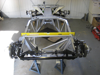
It’s interesting to compare the new back end: 
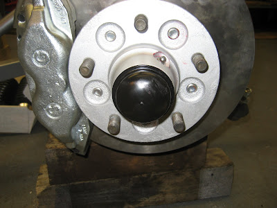
To the original donor item: A veritable phoenix from the ashes!

I finished off by fitting the grease nipples to the rear hubs and greasing all the nipples on the back end.

I’m a little concerned about the track rod end issue – hope it turns out not to be a problem?

Less is More

You'll notice the blog looks different - Had a tidy up and got rid of all the useless distractions - a hangover from when I first started and was just playing and adding everything I could 'cos I thought it was clever.

Cobracam is dead - I had neither the time nor inclination (or a 50 foot USB cable!) to get it in the garage - If someone wants to come round and upgrade my PC to wireless and provide a wireless webcam in the garage they are more than welcome!

Friday 13 April 2007

Same Again

Got home a bit early from work today so managed a quick couple of hours in the garage. Essentially I just repeated the previous exercise on the other side at the front. Lockwire, brake pipes etc. Finished by fitting the braided flexible hoses and tightening all the unions.
To complete things I set the front hub end-floats to the Jaguar spec using a dial gauge as shown below. Whilst I was at it I double checked the brake disc run-out - all was OK.
With the end-floats set I fitted the locking caps and split pins and finally fitted the hub covers.
Job Done!

Wednesday 11 April 2007

Unfinished business up front

Time to finish some of the jobs I've been collecting up front!

First thing to do was to drill the steering arm bolts for lockwire. There have been some posts on the cobraclub forum concerning bolt heads braking off due to inaccurate drilling. This can be a problem if you drill across opposing faces - however if you drill as you would for nuts - i.e across adjacent faces then this does not pose any problems. This would be impossible if it wasn't for this handy little jig:
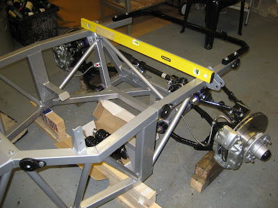
And the finished product: So the steering arm bolts were fitted and torqued up together with the lower calliper mounting bolt. The three bolts were then lockwired as shown which prevents the brake pipe from clashing with the lockwire. Speaking of brake pipes it was time to make some new ones - having re-installed the brake pipe bracket the right way up! This was done pretty easily using 3/16 Kunifer pipe (copper nickel alloy). It is important to put the right flares on the respective ends of the pipe - one end male the other end female. Pipe flaring was again pretty easy (after a couple of practice goes) using the simple flaring tool below - this shows the mandrel ready to be pushed in to form a male or single flare. After this has been formed if the mandrel is removed the 45 degree taper on the screw can be used to form a female or double flare. After a bit of measuring and bending the end result was reasonably neat:But more importantly - on full bump there was sufficient clearance to the upper wishbone arm.Just need to do the same on the other side now.

Wednesday 4 April 2007

Brake Pipe Bracket Dilema? - or not?

Carrying on from the last episode - I swapped over the brake pipe brackets and fitted them upside down. This gave much greater clearance to the rigid brake pipe and fitting. The rigid brake pipe was a replacement Jaguar part and had to be re-bent to suit.
However, after fitting the braided brake hoses it became apparent that the revised positioning was not ideal and the braided hoses had a tendency to kink at as the wheel has turned from lock to lock - it also rubbed on the lower wishbone.Having bent the Jaguar pipe to suit the new arrangement it dawned on me that the problem of it fouling the upper wishbone with the brackets fitted correctly could possibly be solved by re-routing the pipe.

In order to check properly I thought I would fit the steering rack and check the extreme lock positions of the wheel hubs. This was easier said than done as the large rack mounting rubber took copious amounts of hot water, WD40 and bludgeoning before the rack clamp could be fitted properly - this took quite some time.
Having temporarily fitted the rack (it needs to be adjusted for bump steer yet) I found that at the extreme lock positions with the brackets mounted the right way up - if the rigid brake pipe was re-routed there would only be the smallest of clashes with the brake pipe fitting on the bracket and the wishbone. This could only occur with the road spring fully compressed and on the bump stop with full lock applied - never going to happen in reality!

So jobs to do:
  1. Drill the four new steering arm bolts for lockwire

  2. Fit the steering arms and callipers

  3. Make up new rigid brake pipes for the front callipers

  4. Fit the braided brake hoses and check movement

  5. Fit track rod ends

  6. Set toe-in

  7. Correct Bump Steer

I'm Going away for the Bank Holiday Weekend so I've got time to reflect on hopefully getting these things right first time!

Monday 2 April 2007

More Action up front

On Friday I spoke to Andy at GD to confirm the basic static front suspension geometry that I should be aiming for. I subsequently altered the camber shim arrangement at the upper ball joints to give the best fit between the upper wishbone arms. This ended up being 1 x 1.0mm to the rear and 2 x 1.0mm + 1 x 1.6mm to the front. I completed the nearside arrangement - checked the chassis was level and checked the geometry. Both sides had 1/4 degree negative camber and 4.75 degrees castor.


The next stage was to fit the front brake callipers, steering arms and brake pipe brackets. These were temporarily bolted into position as the two replacement steering arm bolts need their heads drilling for lockwire.
It became evident that as the GD steering arm is thicker than the original Jaguar item and therefore that the brake pipe bracket stands too far away from the calliper.
This means that when the rigid brake pipe is fitted there is a potential problem with the pipe being crushed by the upper wishbone arm when the steering is on full lock and the suspension fully compressed - as can be seen in the photo below:One option may be to swap the brackets over from side to side and then use them upside down - this will give about 15mm of additional clearance? - I'll check this out.

I remembered to sort out some replacement rear shock shaft washers - so I'll order them tomorrow so I can finish the rear end off.